Site III.5

Site ID
III.5
Health

COD
2017
Nominal Capacity
110 kWp
Average Specific Yield
996 kWh/kWp
Total Estimated Loss
10.4%
Possible Gain
10% to 12%
CAPEX, OPEX
1.5 ₹/Wp, 0.1 ₹/Wp/a
Expenditure / Energy
N/A
Abstract
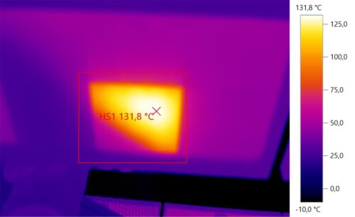
The PV plant is affected by soiling due to city pollution and near shadings caused by surrounding structures. The infrared inspection revealed hotspots induced by different types of shadings. Electroluminescense imaging did not revealed important cracks but exposed a few backsheet scratches. It is recommended to (i) adjust the DC/AC ratio, (ii) shading objects and module relocation and (iii) further monitoring of the module failure types (hotspots, label detachment, browning). The estimated production boost caused by the retrofitting actions lies between 10% and 12%.
Main Findings
Although the cleaning activities were performed the day before the inspection, a few modules were discovered to still have significant amounts of dust.
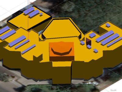
Near shadings effects are caused by shading structures, overhead cables and cooling equipment were visible.
In the DC distribution box II, some cable terminals of the negative pole are burned, likely due to a faulty contact.
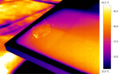
The limited access to the southeast section of the plant is likely the reason why there are footprints on the first module of the table. This will likely induce cell damages and hotspots.
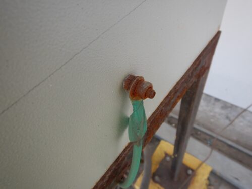
Through visual inspection, browning on the module, backsheet degradation and advance corrosion in the grounding cables (distribution box), among other failure types were exposed.
Electroluminescence imaging did not reveal a significant amount of cracks. However, module backsheet scratches could lead to safety hazards and increased risk of inverter disconnection due to loss of insulation.
Advanced corrosion in the grounding cables might reduce the effectiveness of the insulation.
Impact on Performance
Heavy Soiling
A soiling loss of 5.9% was determined from IV curve measurements of a sample module before and after cleaning.
Estimated Loss
≈ 5.9%
Near Shading
The near shadings are responsible for an irradiation reduction on the tilted plane of approx. 1.5% at the system level.
Estimated Loss
≈ 1.5%
Inverter clipping
Inverter 3 is slightly oversized, leading to overload losses of approximately 3%.
Estimated Loss
≈ 3%
Total Estimated Energy Loss
≈ 10.4%
Proposed Solutions
The module most affected by the shades from the shading structure can be easily relocate. This will reduce the impact of the shadings on the whole string. Furthermore, after the relocation, modules with hotspots (>100°C) shall be monitored to assess the damage and their possible replacement.
Grounding cabling shall be replaced to guarantee a proper grounding throughout the system.
The cleaning cycles shall be increased and defined based on a soiling study that adjusts the cleaning needs to each season. Cleaning once a month during the dry season might not suffice.
A weather station, or at least an irradiation sensor shall be installed on- site to obtain reliable information, i.e., for the plant performance ratio calculation.


