

Site 2.26
Site ID
2.26
Health

COD
2017
Nominal Capacity
50 kWp
Average Specific Yield
1230 kWh/kWp
Total Estimated Loss
11.38%
Possible Gain
5% to 7%
CAPEX, OPEX
1.28 ₹/Wp, 0₹/Wp/a
Expenditure / Energy
1 ₹/kWh to 0.7 ₹/kWh
Abstract
Cables loosely hanging and layout with low bending radius were found. Module misalignment was observed across the installation. It is recommended to (i) optimize cable layout, (ii) carry out cleaning more effectively to remove cementing, (iii) provide better ventilation in the inverter room, (iv) provide safety railings for safer and easier access for the O&M team to modules close to the slopes, and (v) install a weather station or at least an irradiation sensor on the module plane to quantify and monitor the performance ratio. The estimated production boost expected by the retrofitting actions lies around 5% and 7%.
Image gallery


Main Findings

Poor cable management: Loosely hanging cables from the structure. The minimum cable bending radius is not respected.
Inverter fans are soiled.
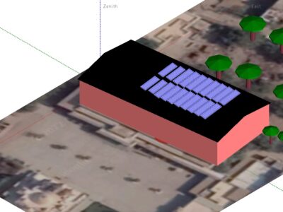
Ballast blocks used are of varying dimensions due to improper casting, PV Plant’s health causing module misalignment.
Tilt inhomogeneity greater than 2 degrees found across the installation.
Modules are clamped at 560 mm from the edge, which does not align with the manufacturer guidelines.
Inverter room was without proper ventilation.
Slope of roughly 20 degrees on both sides of the roof makes the access risky to the end modules for the O&M team.
Unsafe access to the roof.
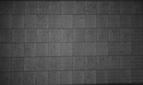
The EL images reveal that the modules are essentially free from defects that can impact the module performance.
Impact on Performance
Heavy Soiling
IR analysis shows presence of hotspots from soiling. The system performance was affected by soiling loss of 2%, estimated from IV curve measurements.
Estimated Loss
≈ 2%
Underperformance
Based on the IV curve measurements, the estimated underperformance is 3.8% for the measured modules.
Estimated Loss
≈ 3.8%
Self Shading
According to PVsyst simulations, the self- shading losses account to 2.25%.
Estimated Loss
≈ 2.25%
Total Estimated Energy Loss
≈ 11.38%
Proposed Solutions
The cable layout shall be optimized; the minimum bending radius is 10x times the cable diameter.
The cleaning shall be carried out more effectively, since soiling is present on the module edges after cleaning.
If possible, the ballast blocks used to fix the mounting structure shall be replaced with proper dimensions, and properly aligned to reduce module misalignment.
The module tilt shall be increased to the optimal value of 25°.
The table pitch used shall be increased to reduce self-shading losses.
The ventilation in the inverter room shall be improved.
A weather station, or at least an irradiation sensor on the module plane shall be installed so that the performance of the system can be properly determined.
Modules shall be clamped according to manufacturer guidelines.
Safety railings shall be provided to reduce safety risks on area close to slope roofs.