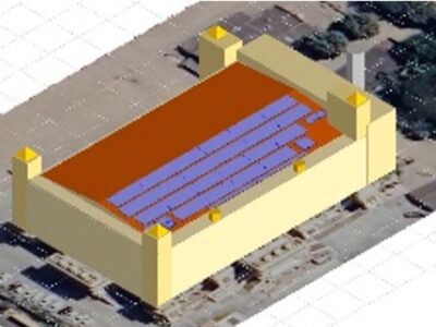
Site 2.23

Site ID
2.23
Health

COD
2017
Nominal Capacity
348 kWp
Average Specific Yield
1324 kWh/kWp
Total Estimated Loss
19.72%
Possible Gain
6% to 10%
CAPEX, OPEX
1.01 ₹/Wp, 0 ₹/Wp/a
Expenditure / Energy
0.6 ₹/kWh to 0.4 ₹/kWh
Abstract
Several modules with cell breakage and isolated cell parts were detected. Cables and connectors were exposed to ambient without any UV protection, they also display signs of abrasion and cuts. Several clamps were improperly fixed, and many were faulty. It is recommended to (i) optimize the cable layout (ii) replace rails that offer better ventilation (iii) restring the modules with cell breakage, and shaded module to dedicated strings, and (iv) install a weather station or at least an irradiation sensor to monitor performance ratio. The estimated production boost expected by the retrofitting actions lies between 6% and 10%.
Main Findings
Poor cable management: Cables and connectors are degraded from exposure to ambient conditions. The cables also showed signs of abrasion and cuts, and low bending radius.
30 mm rail used in flush mount causes higher operating temperatures.
Open shaft holes found on site.
Walkway installed over landscape module, casting permanent shading on the module and reducing string protection.
Clamp fixations at several locations show improper application leading to misalignment and imbalanced loading.
Clamps used to fix walkways are rusted.
Fans and filter in an inverter were heavily
soiled.
Some modules are shaded by a taller section of the building.
Shoeprints found on modules.
IR analysis shows presence of hot cells.
Impact on Performance
Heavy Soiling
The system performance was affected by soiling loss of 3.5%, estimated from IV curve measurements.
Estimated Loss
≈ 3.5%
Cell Cracks
The EL image reveals cracks and isolated parts from broken cells. All modules tested for EL revealed isolated parts. Power loss estimated from mechanical damages is expected to be around 3%.
Estimated Loss
≈ 3%
Underperformance
Based on the IV curve measurements, the estimated underperformance is 7.7% for the measured modules.
Estimated Loss
≈ 7.7%
Near Shading
Simulations from PVsyst revealed near shading losses to be 1.95%, and a 1.34% loss from reduced heat dissipation.
Estimated Loss
≈ 1.95%
Total Estimated Energy Loss
≈ 19.72%
Proposed Solutions
The cable layout shall be optimized, the minimum bending radius shall be 10x the cable diameter, and cable racks shall be used.
Rails used currently of around 30 mm height shall be replaced with ones that offer an effective clearance of 100 mm to facilitate better air flow and improve system performance.
Open shaft holes shall be covered since they pose a several threat to the O&M personnel.
A proper O&M plan shall be established that includes instructions on module handling.
A re-sorting shall be conducted to have modules with isolated parts in the same string or at least same MPPT.
A re-stringing of modules shall be conducted to have shaded modules in the same at least same MPPT.
A weather station, or at least an irradiation sensor on the module plane shall be installed so that the performance of the system can be properly determined.
Faulty clamp fixations shall be properly fixed, and clamps with faulty threads shall be replaced. Rusted clamps should be replaced if possible. To prevent such problems, metal objects vulnerable to corrosion can be painted with zinc.


