

Site 2.20
Site ID
2.20
Health

COD
2018
Nominal Capacity
124 kWp
Average Specific Yield
1090 kWh/kWp
Total Estimated Loss
23.79%
Possible Gain
7% to 9%
CAPEX, OPEX
2.16 ₹/Wp, 0₹/Wp/a
Expenditure / Energy
1.3 ₹/kWh to 1 ₹/kWh
Abstract
Some modules with back-sheet scratches were detected. Cables loosely hanging from the modules were found. Module-to-module earthing is absent. It is recommended to (i) add earthing connections between modules, (ii) replace the cleaning equipment used, (iii) replace modules with back-sheet damage and melted connectors, (iv) replace rusted components of the mounting structure, and (v) install a weather station or at least an irradiation sensor on the module plane to quantify and monitor the performance ratio. The estimated production boost expected by the retrofitting actions lies between 7% and 9%.
Image gallery


Main Findings

Poor cable management: Cables loosely hanging from the structure and exposed to ambient. The minimum cable bending radius is not respected. In addition, table and string labelling are missing.
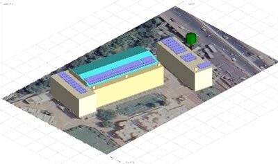
One PV table with a 2-Portrait configuration was set up close to PV tables with 1-Portrait configuration. This causes shading on the 1-Portrait tables.
The joints the mounting structures showed signs of rusting.

A 3.5 m boundary wall casts shadow on the flat-roof installation during the morning, and the sheet-roof installation during the evening.
Tables in one section of installation have bent structures in one end.
Module-to-module bonding is absent.
No weather station identified on site.
Impact on Performance
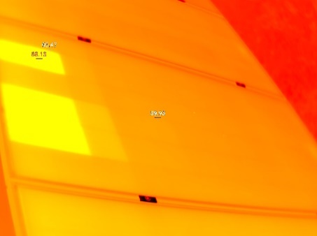
Heavy Soiling
IR analysis shows presence of hot cells from soiling. The system performance was affected by soiling loss of 3.5%, estimated from IV curve measurements.
Estimated Loss
≈ 3.5%

Cell Cracks
The EL image reveals presence of micro- cracks and back-sheet scratches.
Estimated Loss
≈ 2%
Underperformance
Based on the IV curve measurements, the estimated underperformance is 11% for the measured modules.
Estimated Loss
≈ 11.4%
Near Shading
According to the PVsyst simulations, the near shading losses account to 1.56%.
Estimated Loss
≈ 1.56%
Inhomogeneous tilt angle
The module tilt used constitutes to 2.5% losses relative to optimal tilt.
Estimated Loss
≈ 2.5%
Total Estimated Energy Loss
≈ 23.79%
Proposed Solutions
Strings, tables, and inverters shall have suitable labelling (UV-resistant if applicable).
The cleaning cycles shall be increased. Cleaning equipment shall be replaced to provide better cleaning and prevent module damage from cleaning.
Modules with back-sheet scratches and deformed connectors shall be replaced to avoid safety threats.
A re-sorting shall be conducted to have lower performing modules in the same string or at least assigned to individual MPPT.
A re-stringing shall be conducted to have shaded modules in the same string or at least assigned to individual MPPT.
A weather station, or at least an irradiation sensor on the module plane shall be installed.
Module tilt shall be changed to optimal tilt of 27°.
If possible, installation that extend beyond the parapet shall be moved to reduce damage from wind loads.
Earthing connections between modules shall be added.
Rusted clamps and structure shall be replaced if possible. To prevent such problems, metal objects vulnerable to corrosion can be painted with zinc.