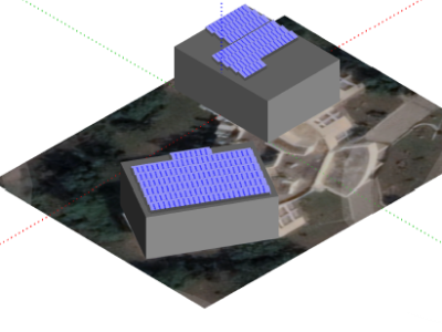
Site 2.17
Site ID
2.17
Health

COD
2018
Nominal Capacity
80 kWp
Average Specific Yield
661 kWh/kWp
Total Estimated Loss
29.26%
Possible Gain
10% to 15%
CAPEX, OPEX
1.40 ₹/Wp, 0.16 ₹/Wp/a
Expenditure / Energy
3.4 ₹/kWh to 2.3 ₹/kWh
Abstract
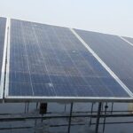
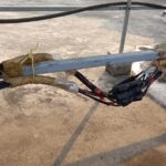
Some modules with mechanical damages were detected (broken modules). Cables hang under the modules were found. Interrow distance is insufficient. Structural earthing is incomplete and corroded. It is recommended to (i) increase the cleaning cycles, (ii) replace damaged modules and cables, (iii) retrofit the mounting structure, (iv) install a new earthing system, and (v) install a weather station or at least an irradiation sensor on the module plane to quantify and monitor the Performance Ratio. The estimated production boost expected by the retrofitting actions lies between 10 and 15%.
Main Findings
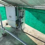
Inverters placed under the modules limiting air circulation.
Base plates, connection bolts and most of the welded areas are rusted.
There is no access to the front side of modules on the upper section for O&M activities.
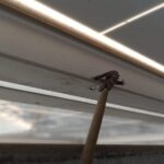
Object on the roof, possible near shading
Broken module.
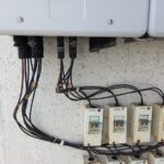
No string labelling on the inverter end.
Burned inverter replaced by a refurbished one.
No weather station on site.
Poor cable management and bad
bonding practice.
Frame of some modules are bent; this can lead to micro-cracks.
Inter-row shading due to proximity of the modules.
Mounting structure is weak, diameter of structure is not ideal.
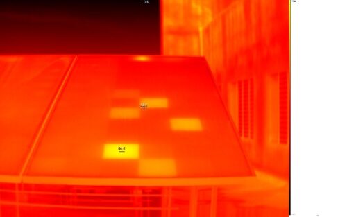
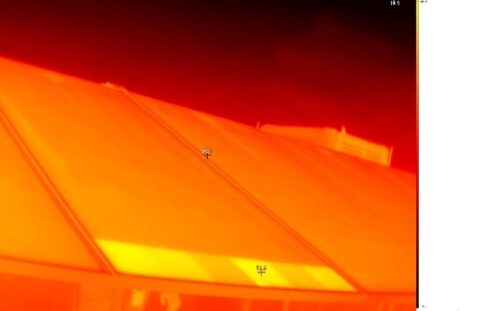
Evidence of PID was found in the IR pictures
Impact on Performance
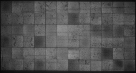
Cell Cracks
Solar modules with defect on the ARC layer; the system is not expected to have large power losses due to this issue.
Estimated Loss
≈ 4%
Heavy Soiling
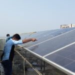
The on-site measured soiling losses were estimated in 3.8%.
Estimated Loss
≈ 3.8%
Self Shading
IR analysis showed that interrow shading developed hot cells in the bottom part of the modules. According to the PVsyst simulation, self-shading losses account for up to 5.36%.
Estimated Loss
≈ 5.36%
Total Estimated Energy Loss
≈ 29.26%
Proposed Solutions
Broken module should be replaced.
Change the location of the inverters in
order to avoid hot spots.
A weather station, or at least a irradiation sensor on the module plane shall be installed so the performance of the system can be properly determined.
The cable layout can be optimized.
Earthing connections between modules
shall be added.
A re-stringing of the modules from the shaded areas shall be conducted in the following way: modules with similar shading conditions shall be installed in the same string or at least assigned to individual MPPTs.
Strings, Tables, and inverters should have a suitable labelling (UV-resistant if applicable).
Rusted clamps and structure should be replaced if possible. To prevent such problems, metal objects vulnerable to corrosion can be painted with zinc.
In case it is possible, interrow distance shall be increased to avoid self-shading.


