Site 2.1
Site ID
2.1
Health

COD
2018
Nominal Capacity
200 kWp
Average Specific Yield
628 kWh/kWp
Total Estimated Loss
67.48%
Possible Gain
5% to 10%
CAPEX, OPEX
1.57 ₹/Wp, 0.12 ₹/Wp/a
Expenditure / Energy
6.9 ₹/kWh to 3.5 ₹/kWh
Abstract
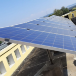
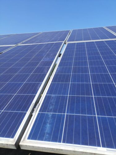
The PV plant shows inhomogeneous amount of soiling. There is evidence of both partially open and broken connectors. Furthermore, the installed system is affected by near shading and the cabling is exposed to UV radiation and sharp edges. It is recommended to (i) replace to broken modules and cables, (ii) install an irradiation sensor (iii) practice frequent cleaning of the modules and the inverter-fan filters, (iv) re-stringing of shaded modules, and (v) yearly thermography inspection of the modules. The estimated production boost expected by the retrofitting actions lies between 5 and 10%.
Main Findings
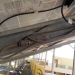
Cable layout and labelling are in bad conditions. In addition, table and inverter labelling is missing. This makes maintenance work difficult and increase losses during O&M work on site.
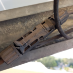
String cables and MC4 connectors are not UV protected and with a high risk of water contact, resulting in isolation issues.
The lightning protection is broken.
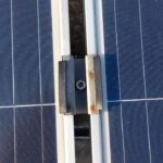
Due to strong winds some clamps were pulled off, resulting in misalignment of modules.
Modules were installed beyond the roof boundary this may cause higher wind loads in some parts resulting in uprooted modules.
The minimum cable bending radius is not met.
Broken, open and burned connector are found on-site.
Impact on Performance
Near Shading
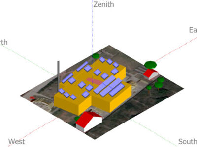
The telephone tower close to the modules produces shading with a particular pattern resulting in hotspots.
Estimated Loss
≈ 1.89%
Cell Cracks
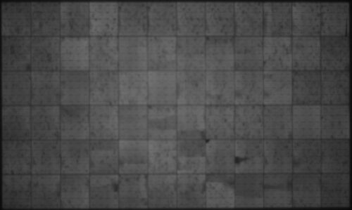
According to the number of cracks discovered via EL imaging; the system is not expected to have large power losses due to inactive areas.
Estimated Loss
≈ 2%
Underperformance
The underperformance of the inspected modules is 60%.
Estimated Loss
≈ 60%
Total Estimated Energy Loss
≈ 67.48%
Proposed Solutions
The cleaning cycles shall be increased based on the results of a soiling study that adjusts the cleaning needs to each season.
Broken modules and cables should be replaced.
UV protection measurements should be taken, it could be by using a suitable cable rack with roof or cable coating.
Cable racks should be separated from the ground to avoid water contact.
The cable layout can be optimized; the minimum bending radius is 10x times the cable diameter.
Strings, Tables, and inverters should have a suitable labelling (UV-resistant if applicable).
A weather station, or at least an irradiation sensor on the module plane, shall be installed so that the performance of the system can be properly determined.
A re-stringing of the modules from the shaded areas shall be conducted in the following way: modules with similar shading conditions shall be installed in the same string or at least assigned to individual MPPTs.


