Site 2.44
Site ID
2.44
Health

COD
2018
Nominal Capacity
300 kWp
Average Specific Yield
1246 kWh/kWp
Total Estimated Loss
25.11%
Possible Gain
11% to 13%
CAPEX, OPEX
1.14 ₹/Wp, 0.12 ₹/Wp/a
Expenditure / Energy
1.3 ₹/kWh to 1.1 ₹/kWh
Abstract
Loosely hanging cables with low bending radius were found. Damaged modules that pose performance and safety threat found on-site. It is recommended to (i) optimize the cable layout, (ii) replace damaged modules, (iii) increase cleaning cycles, (iv) relocate shading objects, (v) re-sort lower performing modules, (vi) retrofit the mounting structure, and (vii) install a weather station or at least an irradiation sensor on the module plane. The estimated production boost expected by the retrofitting actions lies between 10.7% and 12.8%.
Main Findings
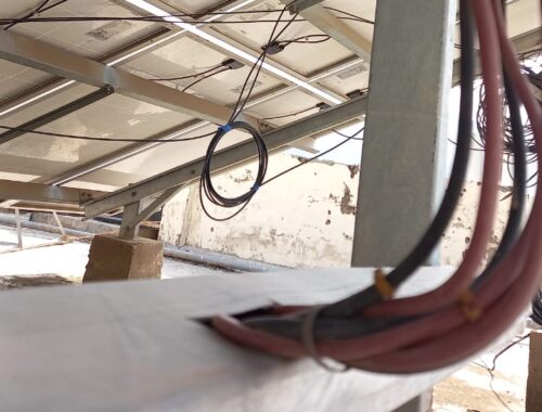
Poor cable management: Loosely hanging cables with low bending radius. Missing string labelling.
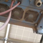
Phase wire contact exposed to ambient.
Inverter fans and filters are soiled.
Modules with broken glass, cell corrosion, damaged backsheet, and burn marks on cell fingers found on site.
Improper roof access.
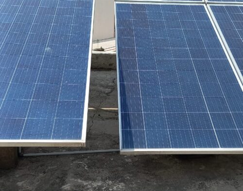
Multiple module orientations and tilts found on site.
Module misalignment due to improper bolting between structure purlins.
Excess structure length observed for a PV table.
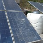
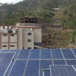
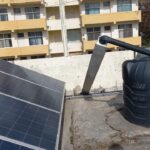
Modules shaded by tables with different tilts, water tanks, and taller rooms and buildings in vicinity of the installation area.
No weather station found on site.
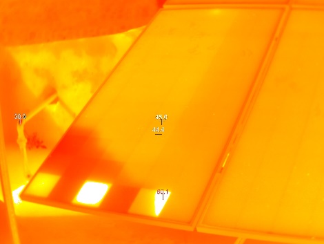
IR analysis reveals presence of hotspots and hot cells from shading by water tank. This may indicate irreversible cell damage.
Impact on Performance
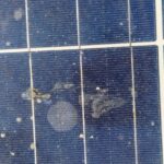
Heavy Soiling
Based on the IV curve measurements, the soiling loss is estimated to be 5.5%.
Estimated Loss
≈ 5.5%
Cell Cracks
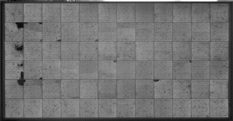
The EL image reveals presence of cracks and isolated parts. These defects are expected to impact performance and generate hotspots.
Estimated Loss
≈ 10%
Underperformance
Based on the IV curve measurements, the estimated underperformance is 3.3% for the measured modules.
Estimated Loss
≈ 3.3%
Near Shading
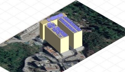
According to PVsyst simulation, the near shading losses account to 2.86%.
Estimated Loss
≈ 2.86%
Total Estimated Energy Loss
≈ 25.11%
Proposed Solutions
Strings, tables, and inverters should have a suitable labelling (UV-resistant).
The cable layout can be optimized; the minimum cable bending radius is 10x the cable diameter.
Cables and wires with exposed contacts shall be immediately replaced since they pose severe safety threat.
The cleaning cycles shall be increased based on the results of a soiling study.
Damaged modules shall be replaced to reduce further performance loss.
A re-sorting shall be conducted to have lower performing modules in the same string, or at least the same MPPT.
A better roof access shall be provided for safer and easier O&M activity.
If the site layout allows, variation in orientations shall be reduced to reduce mismatch losses.
A weather station, or at least an irradiation sensor on the module plane shall be installed.
Structure purlins shall be properly bolted to reduce module misalignment and improve structure functionality. Retrofitting actions shall be done to have structure length align with the table length.
Modules and tables shall be adequately spaced away from shading objects wherever possible to reduce shading losses.


