Site 2.38
Site ID
2.38
Health

COD
2018
Nominal Capacity
10 kWp
Average Specific Yield
1099 kWh/kWp
Total Estimated Loss
26.15%
Possible Gain
8% to 10%
CAPEX, OPEX
1.61 ₹/Wp, 0.20 ₹/Wp/a
Expenditure / Energy
3.3 ₹/kWh to 2.5 ₹/kWh
Abstract
Cables with low bending radius were found. Several issues concerning mounting structure and components were observed. It is recommended to (i) optimize the cable layout, (ii) increase cleaning cycles, (iii) retrofit the mounting structure, (iv) add module to module equipotential bonding, and (v) relocate shaded module tables, and (vi) install a weather station or at least an irradiation sensor on the module plane. The estimated production boost expected by the retrofitting actions lies between 7.7% and 10%.
Main Findings
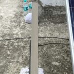
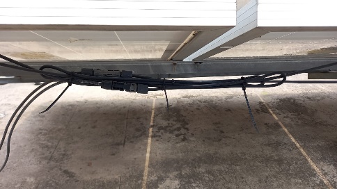
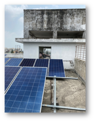
Poor cable management: Cables with low bending radius. Missing string labelling at the module end.
Connectors are mildly degrading due to exposure to ambient.
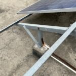
Screws, nuts, and earthing strips used in the structure are rusted.
Module to module equipotential bonding missing.
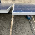
Some vertical posts used in the mounting structure are not perpendicular, causing module misalignment.
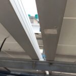
L mounting plates used to fix structure purlins are improperly mounted.
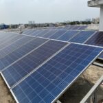
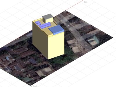
The longer table with 12 modules are shaded by a room very close to it. The smaller tables are significantly shaded by both room and parapet wall.
No LA found on site.
No weather station identified on site.
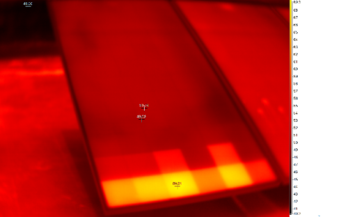
IR analysis reveals hot cells due to cementing.
Impact on Performance
Heavy Soiling
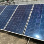
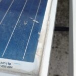
Based on the IV curve measurements, the soiling loss is estimated to be 5.6%. Some modules are soiled from bird dropping, and cementing.
Estimated Loss
≈ 5.6%
Cell Cracks
The EL image reveals presence of few micro-cracks and soldering issues from manufacturing. These cracks are not expected to impact performance in their given state.
Estimated Loss
≈ 2%
Underperformance
Based on the IV curve measurements, the estimated underperformance is 6.7% for the measured modules.
Estimated Loss
≈ 6.7%
Near Shading
According to PVsyst simulation, the near shading losses account to 3.6%.
Estimated Loss
≈ 8.21%
Total Estimated Energy Loss
≈ 26.15%
Proposed Solutions
Strings, tables, and inverters should have a suitable labelling (UV-resistant).
The cable layout can be optimized; the minimum cable bending radius is 10x the cable diameter.
Cleaning shall be conducted more effectively since module soiling is present despite weekly cleaning frequency reported by the on-site team.
Inverter shall be cleaned frequently.
If possible, the smaller tables shall be relocated to the top of a taller room, and the longer table with 12 modules shall be moved slightly away from the room that causes shading.
LA shall be installed on site.
A weather station, or at least an irradiation sensor on the module plane shall be installed.
Earthing connections between modules shall be added.
Rusted components and structure shall be replaced if possible. Vertical posts shall be realigned to reduce module misalignment. To prevent such problems, metal objects vulnerable to corrosion can be painted with zinc.


