Site 2.51
Site ID
2.51
Health

COD
2017
Nominal Capacity
100 kWp
Average Specific Yield
604 kWh/kWp
Total Estimated Loss
31.41%
Possible Gain
13% to 63%
CAPEX, OPEX
2.45 ₹/Wp, 0.12 ₹/Wp/a
Expenditure / Energy
3 ₹/kWh to 0.6 ₹/kWh
Abstract
Broken cables, exposed wires, and faulty system components were observed. Several damaged modules found on site. It is recommended to (i) improve cleaning activity, (ii) replace broken cables (iii) replace faulty components and inverter, (iv) replace damaged modules, (v) retrofit the mounting structure, (vi) re-sort the lower performing modules, and (vii) install a weather station or at least an irradiation sensor on the module plane. The estimated production boost expected by the retrofitting actions lies between 13.2% and 63.2%.
Main Findings
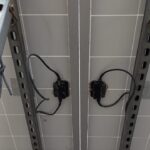
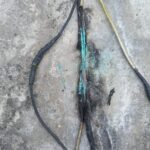
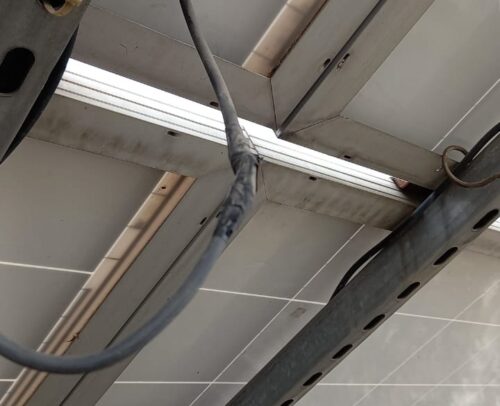
Poor cable management: Cables in extremely poor condition. Insulation tapes used to fix broken cable and exposed wires. Wrong cable type used in strings.
3 modules removed from string which were not replaced.
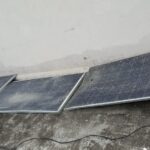
Modules with broken glass and damaged and burned backsheet connected to system.
One of the two inverters non-functional since two years with burnt cable and fuse.
Mains Air Circuit Breaker (ACB) not secured.
Insufficient gap between modules.
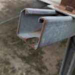
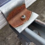
Clamps used in structure rusted. Structure purlin edges are sharp and not secured.
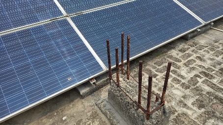
Modules shaded by iron rods in front of modules.
No weather station found on site.
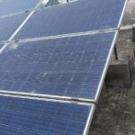
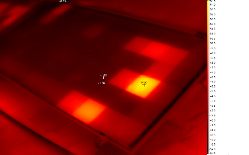
IR analysis reveals hot cells from soiling.
Impact on Performance
Heavy Soiling
The system performance was affected by soiling loss of 3.5%, estimated from IV curve measurements.
Estimated Loss
≈ 3.5%
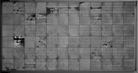
Cell Cracks
The EL image reveals presence of cracks and isolated parts. These defects are expected to impact performance and generate hotspots.
Estimated Loss
≈ 10%
Underperformance
Based on the IV curve measurements, the estimated underperformance is 10.2% for the measured modules.
Estimated Loss
≈ 10.1%
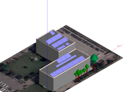
Near Shading
According to PVsyst simulation, the near shading losses account to 1.59%.
Estimated Loss
≈ 1.59%
Total Estimated Energy Loss
≈ 31.41%
Proposed Solutions
Strings, tables, and inverters should have a suitable labelling (UV-resistant).
Broken cables and exposed wires shall be immediately replaced due to serious safety concerns.
The 3 modules removed from the string shall be replaced.
Damaged modules shall be replaced since they pose both performance and safety threat.
Non-functional inverter shall be investigated further for root-cause and get replaced to fully utilize the generation. Observed faulty safety components such as the ACB, and fuses shall also be replaced.
A re-sorting shall be conducted to have lower performing modules in the same string, or at least the same MPPT.
The iron rods in front of the modules shall be relocated to avoid hotspot from permanent shading.
Rusted clamps used in the structure shall be replaced. To prevent such problems, metal objects vulnerable to corrosion can be painted with zinc. Sharp edges on purlins must be secured to improve safety of O&M personnel.
A weather station, or at least an irradiation sensor on the module plane shall be installed.


