Site 2.36
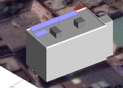
Site ID
2.36
Health

COD
2018
Nominal Capacity
5 kWp
Average Specific Yield
1100 kWh/kWp
Total Estimated Loss
42.39%
Possible Gain
7% to 12%
CAPEX, OPEX
8.17 ₹/Wp, 0. ₹/Wp/a
Expenditure / Energy
4.9 ₹/kWh to 2.7 ₹/kWh
Abstract
Loosely hanging cables with low bending radius were found. Modules with manufacturing issues found on site. It is recommended to (i) optimize the cable layout, (ii) relocate the tables, (iii) replace damaged modules and re-sort lower performing modules, (iv) retrofit the mounting structure, (v) add module to module equipotential bonding, and (vi) install a weather station or at least an irradiation sensor on the module plane. The estimated production boost expected by the retrofitting actions lies between 6.6% and 11.9%.
Main Findings
Some cable conduits are broken.
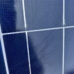
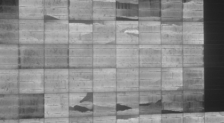
Manufacturing issues of busbar misalignment, delamination, and soldering paste on cell observed on modules.
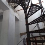
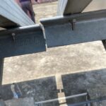
Improper access to the site.
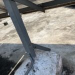
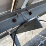
Angle beam disconnected from structure
rafter and post.
Module misalignment observed due to improper fixation of L brackets.
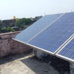
Modules installed in the west side are very close to the parapet wall, making accessibility challenging.
Screws and nuts used in the structure are rusted.
Some modules are shaded by the water storage tank and the parapet wall.
No weather station found on site.
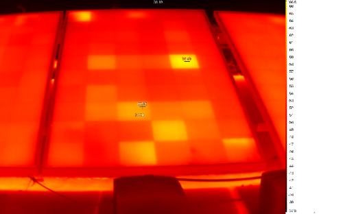
IR analysis reveals presence of warm and hot cells. This may be correlated with the defects revealed in EL imaging.
Impact on Performance
Heavy Soiling
Based on the IV curve measurements, the soiling loss is estimated to be 2.2%.
Estimated Loss
≈ 2.2%
Cell Cracks
The EL image reveals presence of cracks, isolated parts, and dark cells indicating issues from transportation or handling. These defects generate hotspots and pose both performance and safety threat.
Estimated Loss
≈ 10%
Underperformance
Based on the IV curve measurements, the estimated underperformance is 26.9% for the measured modules.
Estimated Loss
≈ 26.9%
Near Shading
According to PVsyst simulation, the near shading losses account to 2.02%.
Estimated Loss
≈ 2.02%
Total Estimated Energy Loss
≈ 42.39%
Proposed Solutions
Strings, tables, and inverters should have a suitable labelling (UV-resistant).
The cable layout can be optimized using cable racks to prevent cables from loosely hanging and also avoid water contact.
Modules severely damaged with isolated parts shall be replaced to reduce further performance loss.
A re-sorting shall be conducted to have lower performing modules in the same string or at least assigned to individual MPPT.
A weather station, or at least an irradiation sensor on the module plane shall be installed.
If possible, tables shall be moved away from the parapet wall and the water storage tank to address the problem of challenging accessibility and shading, since there is sufficient area on the roof.
Angle beam connection to the rafter shall be redone.
L brackets shall be properly fixed so that the module misalignment is reduced.
Rusted components of the structure shall be replaced if possible. To prevent such problems, metal objects vulnerable to corrosion can be painted with zinc.


