Site 2.33
Site ID
2.33
Health

COD
2018
Nominal Capacity
10 kWp
Average Specific Yield
1203 kWh/kWp
Total Estimated Loss
15.94%
Possible Gain
6% to 10%
CAPEX, OPEX
5.87 ₹/Wp, 0 ₹/Wp/a
Expenditure / Energy
3.7 ₹/kWh to 2.2 ₹/kWh
Abstract
Cables with low bending radius found. Modules with damaged backsheet found on site. It is recommended to (i) optimize the cable layout, (ii) conduct cleaning more effectively, (iii) replace backsheet damaged modules, (iv) add module to module equipotential bonding, (v) retrofit mounting structure, and (vi) install a weather station or at least an irradiation sensor on the module plane. The estimated production boost expected by the retrofitting actions lies between 6% and 10%.
Main Findings
Poor cable management: Cables with low bending radius. Cables and connectors are degraded, and string labelling is missing.
Module to module equipotential bonding missing.
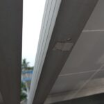
Module back-sheets indicate presence of chalking. Cuts and backsheet burns were observed.
Cell delamination observed in several modules.
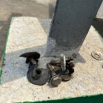
Rubber washers used for module fixation on purlins.
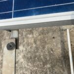
Surface cracking observed in installation area due to excess structure weight.
L channel purlins deformed from handling or transportation.
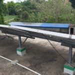
Uneven spacing between ballast blocks cause sagging, and modules are fixed improperly on the purlins, both causing module misalignment.
No LA found on site.
No weather station identified on site.
IR analysis reveal hot cells, mostly due to module cementing.
Impact on Performance
Heavy Soiling
Based on the IV curve measurements, the soiling loss is estimated to be 2.7%. Modules show presence of cementing.
Estimated Loss
≈ 2.7%
Cell Cracks
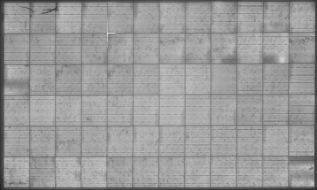
The EL image reveals presence of back sheet scratches and long cracks. Back sheet scratches may pose performance and safety threat.
Estimated Loss
≈ 6%
Underperformance
Based on the IV curve measurements, the estimated underperformance is 5.1% for the measured modules.
Estimated Loss
≈ 5.1%
Near Shading
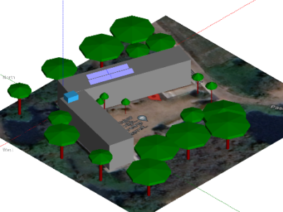
According to PVsyst simulation, the near shading losses account to 1.54%.
Estimated Loss
≈ 1.54%
Total Estimated Energy Loss
≈ 15.94%
Proposed Solutions
Strings, tables, and inverters should have a suitable labelling (UV-resistant).
The cable layout can be optimized; the minimum cable bending radius is 10x the cable diameter.
Cleaning shall be carried out more effectively to address cementing.
Modules with backsheet scratches shall be replaced since they pose a severe performance and safety threat.
Earthing connections between modules shall be added.
Rubber washers used for module fixation shall be replaced with suitable weather resistant EPDM washers.
A re-sorting shall be conducted to have lower performing modules in the same string or at least same MPPT.
Surface levelling shall be re-done to address surface cracking.
If possible, the ballast blocks shall be redone to have even spacing and reduce losses from module misalignment.
Retrofitting actions on the structure shall be done be to have deformed purlins replaced.
LA shall be installed on site.
A weather station, or at least an irradiation sensor on the module plane shall be installed.


